[Date Prev][Date Next][Thread Prev][Thread Next][Date Index][Thread Index]
Power Cart Failure - What Caused It?
Hi,
As some of you know, a couple of weeks ago we had a catastrophic failure during our
downtown run which burned out several components in the power cart. Some of the
damaged components have been replaced and the others are on order. The
layout is completely operational - we just can't read the current flow on track 2.
Here is the scenario at the time of the failure:
1. Tracks 1, 2, and 4 had trains running on them.
2. Allan tried to run his passenger train on track 3 and kept tripping the circuit
breaker. We decided to try the high power transformer.
2. We put the high power transformer on track 3.
3. Allan turned up the power. As the voltage increased, the current flow also
increased. When the current reached about 6 amps, the circuit breaker
in the power monitor tripped. We flipped the toggle switch in the power
monitor to bypass the circuit breaker (relying on the 15 amp circuit breaker
with the transformer and the 15 amp circuit breaker in the TPC to shut down
the power in case of a derailment) and tried again. We then saw the same
behavior - as Allan turned up the voltage, the current increased. Allan called
my attention to the fact that the ammeter was reading 16 amps.
4. Out of the corner of my eye, I thought I saw the LEDs for tracks 1 and 2 flash white.
We then smelled something burning.
5. The operators of the trains on tracks 1, 2, and 4 started reporting that they had
lost control of their trains.
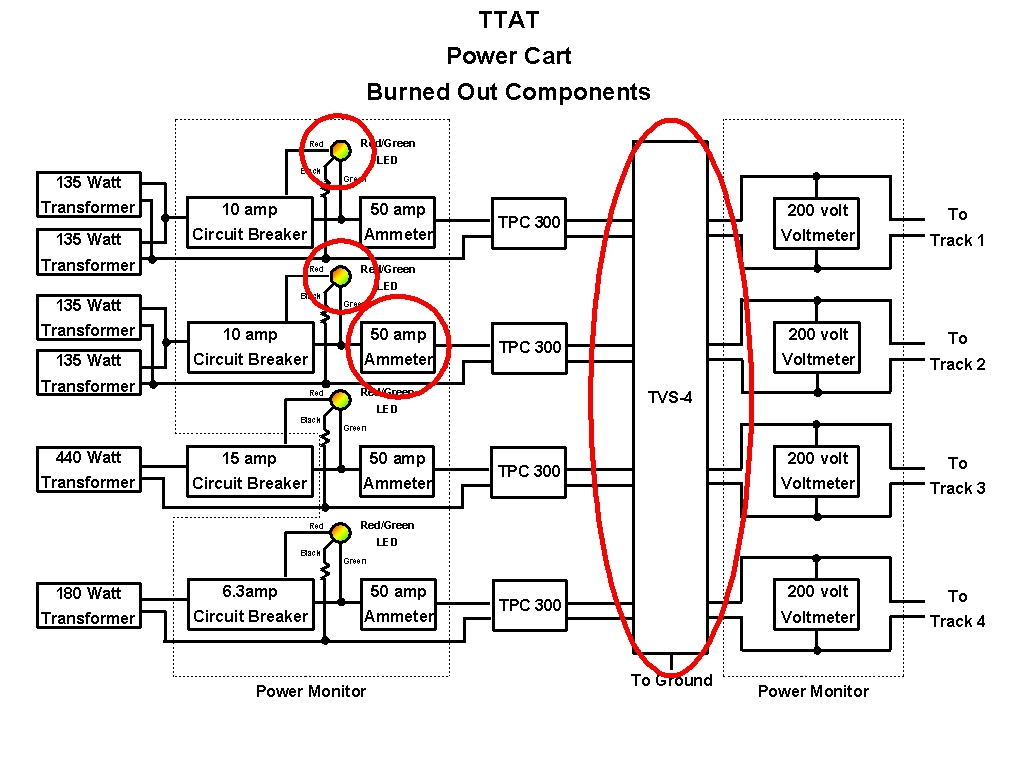
6. We shut down the system and started to investigate. The TVS-4 surge protector
was hot to the touch and the case appeared to be melted. We disconnected
the TVS-4 and fashioned jumper cables to reconnect the TPCs to the track feed wires.
7. The following week, I took the Power Monitor home and verified that the red/green LEDs
for tracks 1 and 2 were burned out. I also determined that the ammeter for track 2
was not reading properly (i.e. it was reading 35 amps) and, whenever it was plugged
into the Power Monitor, tracks 1 and 2 appeared to be shorted together. I replaced the
burned out LEDs and left the track 2 ammeter unplugged pending acquiring a replacement
meter.
8. I contacted Scott's Odds-N-Ends about the TVS-4. Their engineer sent me the schematic
diagram for the TVS-4, explained how it worked, and implied that the ground terminal
shouldn't be connected to earth ground. I will get back to him for a better explanation.
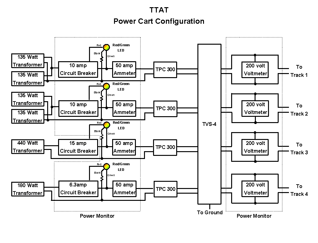
I attached two drawings to this note. The first is the configuration of the power cart at the
time of the failure. The second diagram is the same configuration with the
damaged components circled in red. I also attached the schematic for the TVS-4.
I would like anyone with any knowledge about electrical circuits, and especially model
train wiring, to look at the diagrams and come up with a plausible theory as to what
happened. I am completely stumped. My initial thought was that the TVS-4 was
overloaded by the high current on track 3 and burned out. However, my analysis of
the TVS-4 shows that all four of the transorbs (the components which are supposed to
detect voltage spikes and short them to ground) which were connected to the hot lines
(one for each track) are burned out. The circuit board shows more scorching around
the transorb for track 1, less for track 2, and little scorching for tracks 3 and 4.
The transorbs connected to the neutral lines are undamaged.
If the transorb for track 3 burned out due to the high current flowing to track 3, how did
the other transorbs get burned out? And, what could possibly cause the LEDs for
tracks 1 and 2, and the ammeter for track 2, to fail? Even if the TVS-4 caused
a power surge when it failed, it couldn't get a high voltage spike through the TPCs
back to the LEDs and ammeters. This just doesn't make any sense.
The only explanation I can come up with is that coincidentally with our use of the
new transformer there was a power surge in the building's power system. Perhaps
the A/C system kicked on or off and caused a surge. This could have caused a
high voltage spike at the imput to the transformers, which could have also caused
a corresponding voltage spike at the outputs, which eventually got to the TVS-4
and burned it out. This theory also has some problems. If there really was a
high voltage spike, and a high current flow, why didn't any of the circuit breakers
trip? There are circuit breakers in each transformer, in the power monitor (except
for track 3), and in the TPCs. Why did only the LEDs for tracks 1 and 2 fail?
(Perhaps because there are two transformers for each track?) Why did a
35 amp AC ammeter on track 2 fail? There is no way any of our transformers
could possibly supply 35 amps.
I am completely mystified. If anyone can come up with a plausible theory
as to what happened, please share it with us. If we can figure out what
happened, perhaps we can protect the layout from a similar occurance in
the future.
Thanks.
Ira
TVS Schematics.pdf